This tutorial will guide you through the process of connecting Fixposition Vision-RTK 2 to Leo Rover.
This tutorial will guide you through the process of connecting Fixposition Vision-RTK 2 to Leo Rover.
Fixposition Vision RTK2 is a great GPS module capableof achieving up-to a centimeter-level accuracy. This system leverages Real-TimeKinematic (RTK) and vision-based positioning technology to provide precise localization even in challenging environments. With its compact design VisionRTK2 empowers Leo Rover users to navigate with unparalleled accuracy, unlocking new possibilities for research, exploration, and industrial applications.
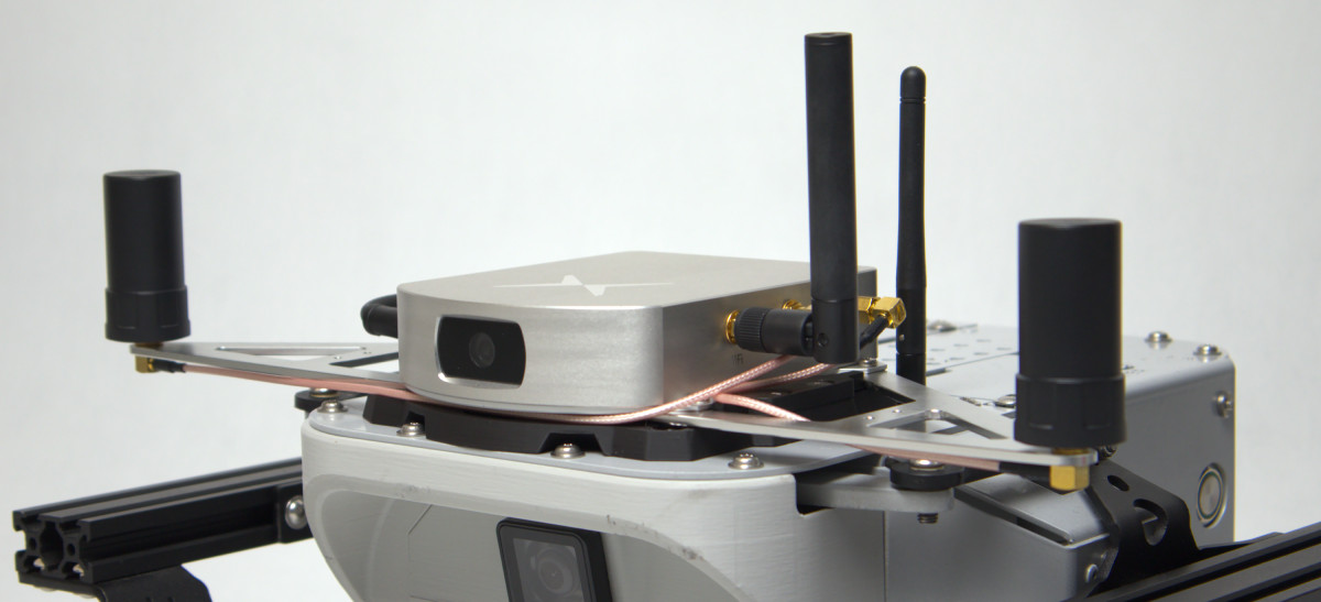
The module needs to be attached to the rover in a spot that provides anuninterrupted view of the terrain.
The accuracy of the system depends on how far apart the GNSS antennas are spaced. Since Leo Rover is rather small it might be hard to place them more than 30cm apart. The system provides a satisfactory accuracy with setup like this, but it's not advised to go even lower. If your project allows it, try to position the antennas even further apart. It's also a good choice to move the GNSS antennas away from any parts of the rover that might be a source of electromagnetic interferences (e.g. motors).
The only wire needed for the module to work is a powercable. An external power distribution module like our Powerbox might come in handy in this case. Connecting the power wire straight to the rovers battery is theoretically possible, but not advised.
Having configured the sensor, and connected to the rover, the only thing that we need to do is integrate the sensor's data into ROS system running on the rover.
For this task we need to install the fixposition ROS driver into our ROS workspace, therefore log in using ssh to the rover, and enter the directory with package sources in your workspace:
Then download the GitHub repository with the driver:
As the repository also contains sources of packages for ROS2 we can remove them:
Now we need to build the package, so go back to the ROS workspace and execute those commands:
Once the packages are installed, we need to do some configuration for the driver to work properly. First we have to change the `ip` parameter in the `tcp.yaml`file to the sensor's IP address in the rover network, so it should look like this:
As we are going to provide wheel odometry data for the sensor from our robot, we have to configure also the odometry converter. In the`odom_converter.yaml` file we have to put the correct topic type and name and chose to use the angular data from the topic too. We will use the`/odometry_merged` topic of type `Odometry` with the angular data, therefore the parameters will be:
Now, the last part of the configuration is to include the correct launch file in the main launch file. As the sensor is connected with the rover through Wi-Fi, we need to launch the TCP related files. Therefore you need to comment and uncomment correct lines in `driver_with_odom_converter.launch` file. It should look like this:
With such setup it is okay to launch the nodes, but we need to enable the data flow from the sensor, therefore you need to enable couple of options in the Input/output part of the fixposition webUI. To be more specific, you must enable those options on some TCP port (e.g., TCP0):
Now it's also convenient to launch this node at the robot's start-up so we don't have to do this manually. There is also one problem with `tf` framespublished by the fixposition ROS driver - at this point it's not connected to Leo's `tf tree`. To connect the frames, we will use static transform publisher,which needs to be launched every time with the driver. Therefore, we will make one launch file and cover both functionalities in it. Usual location for suchfiles is `/etc/ros` directory and we will place the file there.
And we must include it inside the main launch file on the robot (add thisline somewhere in between the `launch` tag):
Find us on:
