In this tutorial, we will show you how to connect Marvelmind Indoor GPS system with Leo Rover.
In this tutorial, we will show you how to connect Marvelmind Indoor GPS system with Leo Rover.
Marvelmind Indoor Navigation System is an off-the-shelf indoor navigation system, designed to provide precise (±2cm) location data to autonomous robots, vehicles (AGV), and copters. It can also be used to track moving objects via mobile beacons attached to them. Other applications include, for example, forklifts, virtual reality (VR) systems, helmets for construction workers or miners, etc.
For the purpose of this tutorial, we have prepared leo_marvelmind package which makes use of Marvelmind ros packages to provide the rover's estimated position, from the Marvelmind system. You won't have to write a single line of code, but some configuration may need to be tweaked to work best in your environment.
Make sure you are operating on the newest image for the Raspberry Pi and you are up-to-date with the packages and have the newest firmware flashed.
You will also need to have ROS installed on your computer and some previous experience with ROS is also recommended.
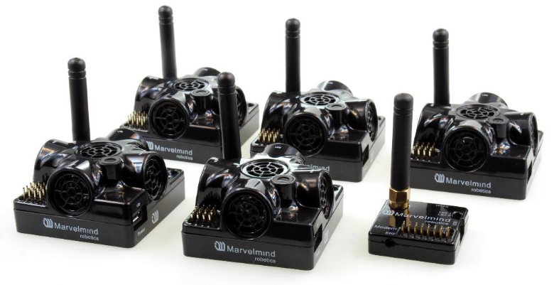
In this tutorial, we integrate Marvelmind Starter Set Super-MP-3D consisting of:
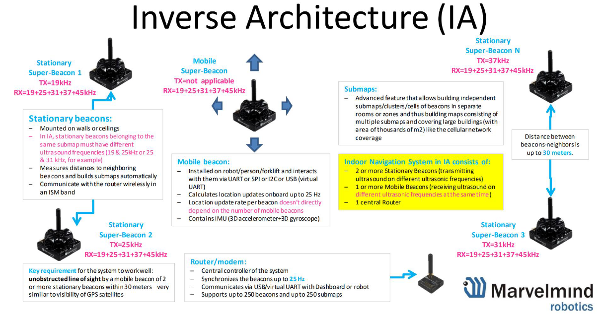
Marvelmind provides a few architectures for their system. This tutorial is configured for Inverse Architecture (IA):
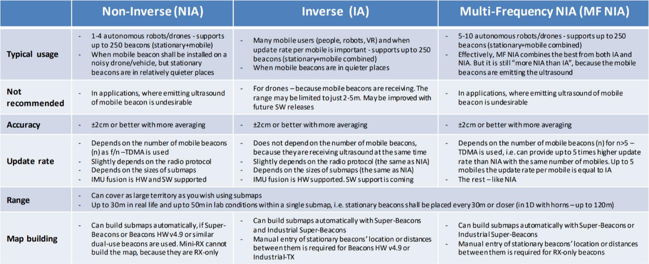
Here is a quick comparison of the architectures:
You can find some more information in this and FAQ section on the Marvelmind page.
In order to use Marvelmind system for navigation, you need Marvelmind API and their software. In the software, you can find the newest firmware for the beacons and modem, and API is needed to upload it to the device.
To download the requried files, you can go to Marvelmind page with downloads, and find the newest package, or download it from here.
Once you have downloaded the package, you need to unzip it. On Linux, it can be done with the unzip command line tool. In terminal, just go to the directory where the zip file has been downloaded (default is ~/Downloads) and type:
Then, in the extracted directory, go to Dashboard/linux. The next directory you need to choose based on your computer's architecture (for us it was x86).
You can check what your architecture is with:
Or:
Then, go to the specified directory, and give execution rights to dashboard_<computer architecture> file:
First, charge all the beacons with a USB cable (full charging takes 2–4 hours).
Run the dashboard by typing in the correct directory
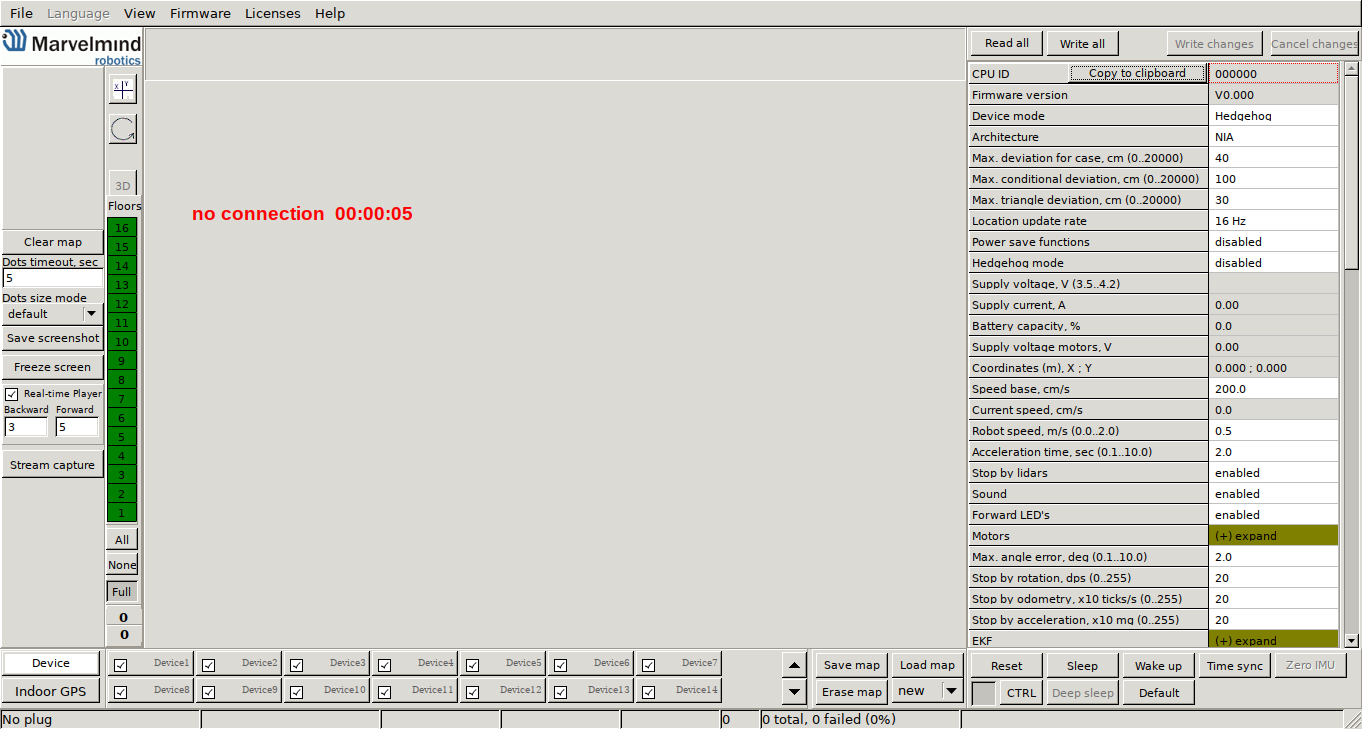
You should see something like this:
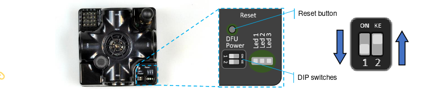
Now, you need to turn on your beacons (or just the currently upgraded ones not to waste the battery in other beacons) by placing the DIP switches like it is shown below:
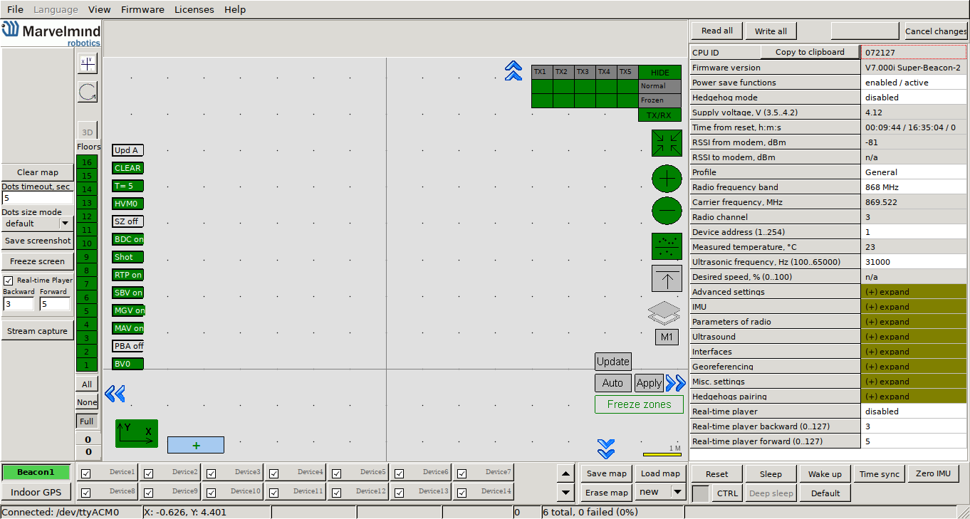
Now, connect the beacon to the computer with the USB cable. Once it is found, your screen should change to something like this:
If your beacon is connected, go to Firmware -> Upload firmware. You should see a new window.
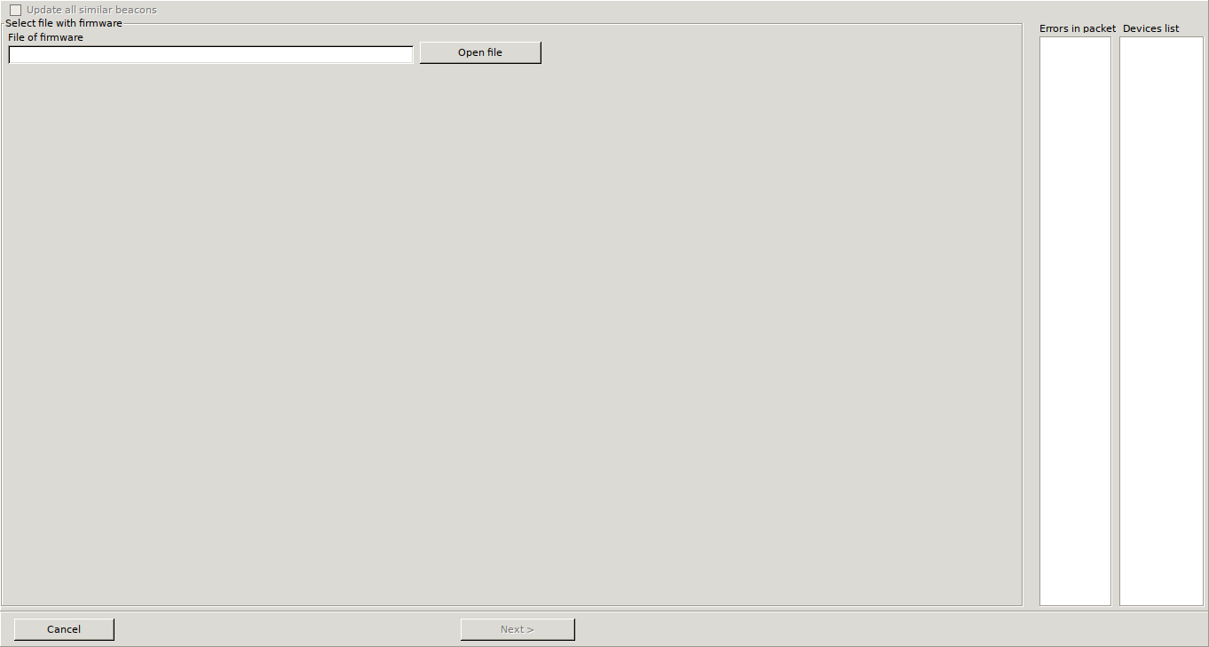
Click Open file and choose the correct firmware file. As we are integrating for Inverse Architecture, choose from the base directory of unzipped package Software_ia. Then, choose super_beacon_ia (if you have some other type of beacon, choose the directory for your device). From there, choose the .hex file (there should be only one in the directory) and click Open. Then, click the Next button in the bottom part of the window, and the firmware upload will start.
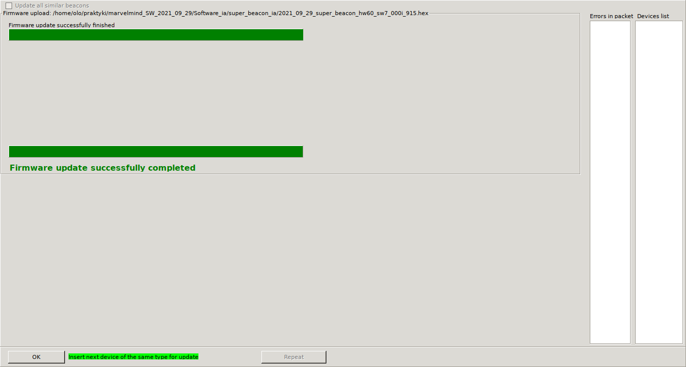
When the update is complete, you will see something like this:
If you have any problems with HEX programming, use DFU. Full instruction can be found here on page 109.


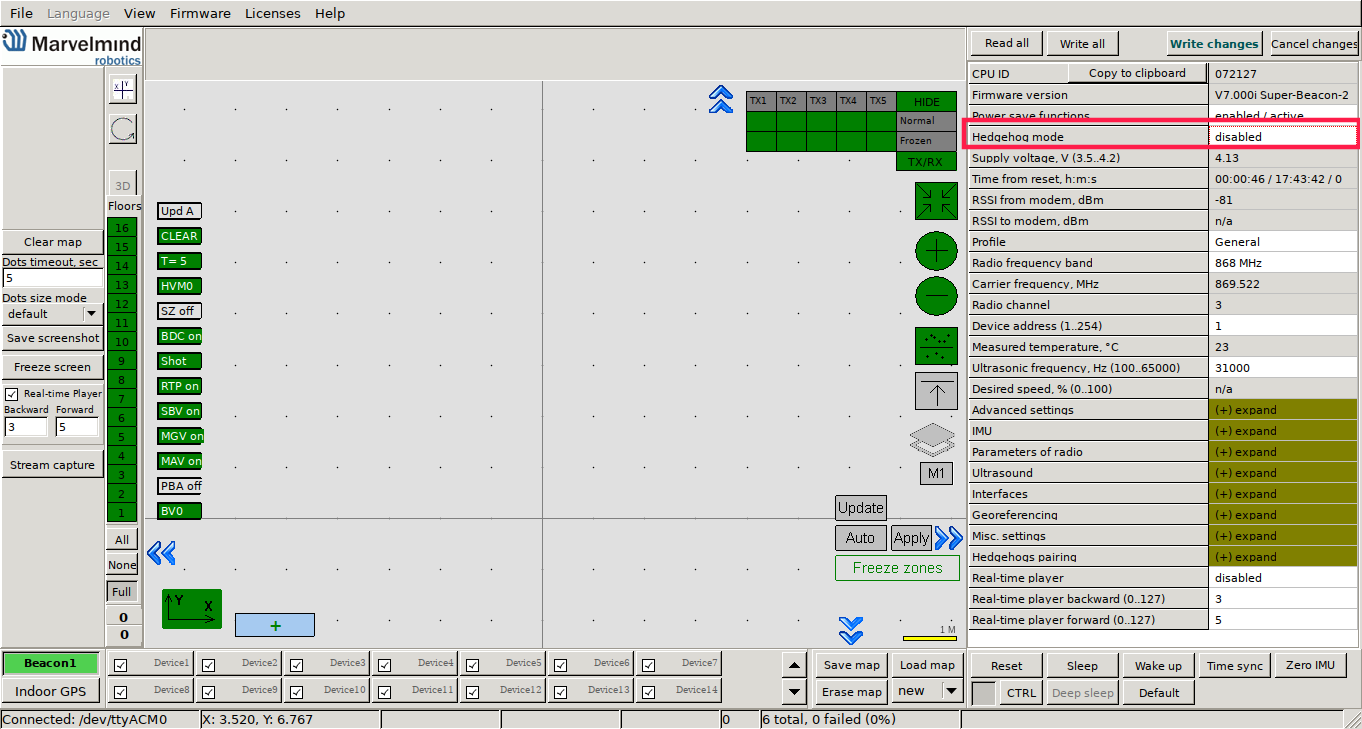
To save changes, press Write changes in the upper right part of the dashboard, and reset the device (the button above the DIP switches for beacon; the button on the side – for modem).
With each beacon, there is a velcro in the box. You need to attach one part to the beacon, and the other to the wall.
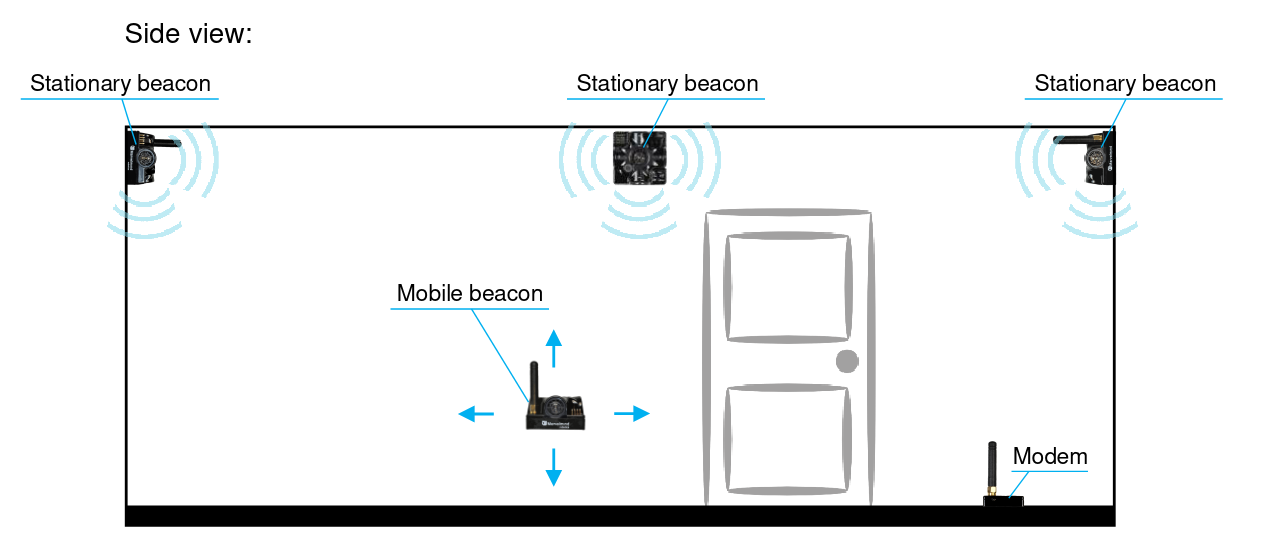
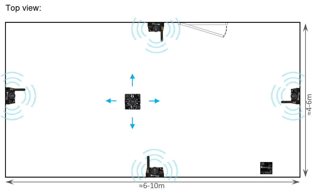
Place the stationary beacons high on the walls vertically in a way that will provide optimal ultrasonic coverage (make sure that the antenna is in the upper right corner of the beacons).
Measure the height at which the beacons are placed, as we will need it for future change in settings.
Here is a video with additional instructions on installing the beacons on the walls.
Possible setup:
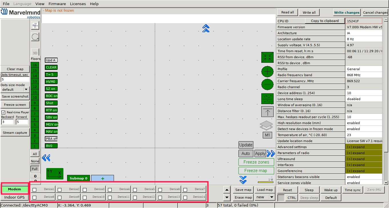
If you have turned off the dashboard, turn it on and connect the modem to your computer. Turn on all the stationary beacons. Now, you need to wake them up. In the dashboard, with the connected modem (in the lower left corner, the modem should be shown as connected), in the lower part of the dashboard, there are numbers of devices. Double click on a number to wake up a device with a given number.
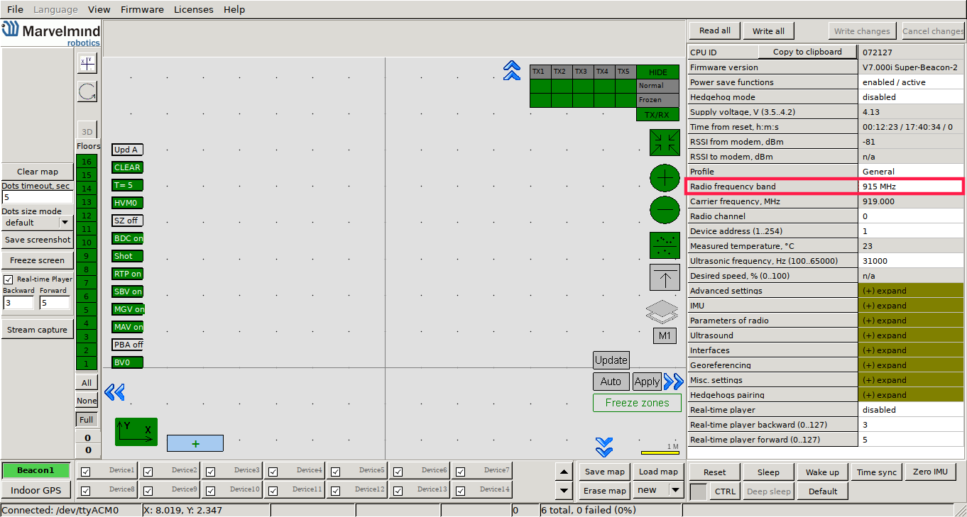
Now, when the beacons are turned on, the system may run the frequency search if it is the very first time you are waking up the beacons.
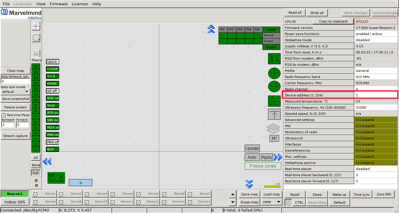
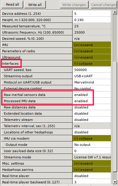
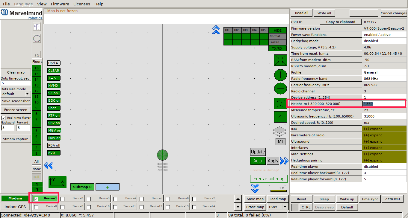
Now, by clicking on the woken device, you can see and change its options (you can check RSSI, voltage, ultrasonic filter settings, etc.) on the panel in the right part of the Dashboard.
For each beacon you have turned on, enter the height it's placed at.
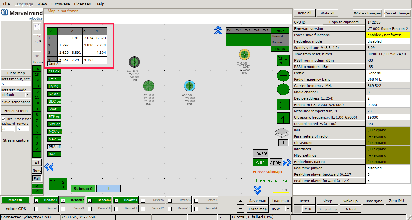
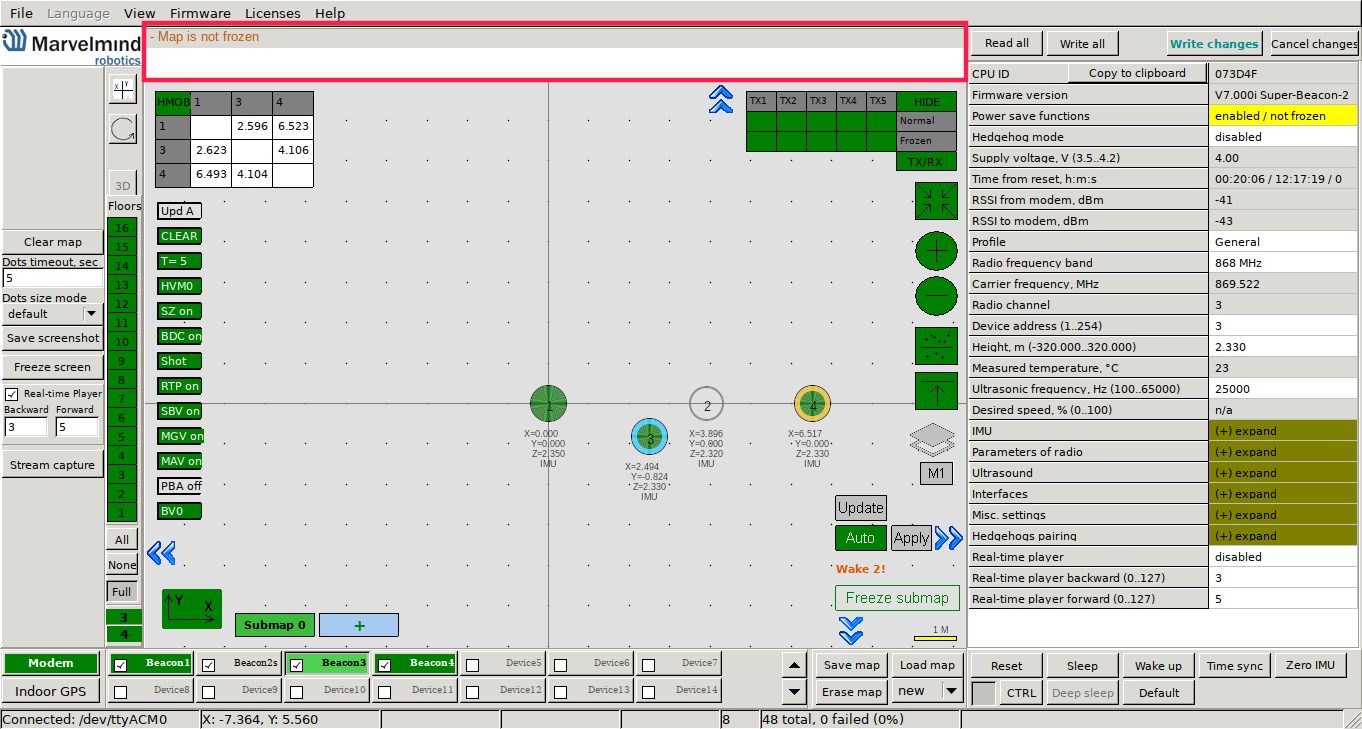
At this moment, the map should zoom in and form automatically. If the map didn't form well, check the table of distances in the upper left corner.
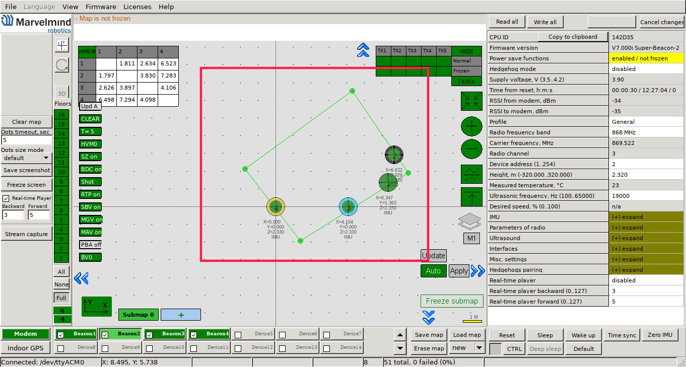
Next, you need to make the service zone. To do so, just press Shift + Left mouse button on the map to add a point (press the same combination on a point to remove it). Two points will form a line; three and more – a polygon. In the end, you should have something like this:
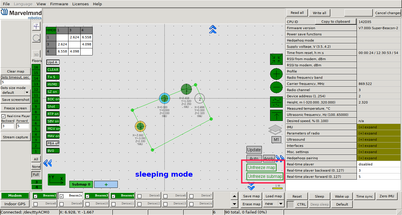
The last step is to freeze the submap and the map (provided that everything in the previous steps was good). When you freeze the map, stationary beacons will stop measuring relative distances and will be ready to measure distance from the mobile beacon.
If in the table you see some empty cells (except for the cells on diagonal) or marked yellow/red, it is an indication that distances between some beacons are measured inconsistently or are not measured at all. Try re-positioning them because usually there is an obstruction of some sort between the beacons.
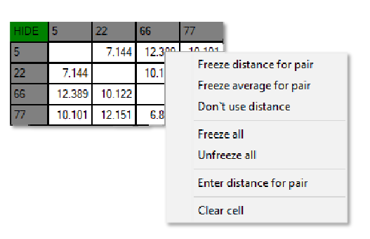
You can also input the distance between beacons manually. To do so, just right-click on a cell that corresponds to a given pair of beacons, then, choose Enter distance for pair. After that, you can also freeze the distance for that pair (or you can later freeze the whole submap at once).
Here are the meanings of possible cell colors:
It's also worth considering the diagnostic messages in the upper part of the Dashboard. There, you can find important system’s messages which may contain a lot of useful information (for example, a message about repeating beacon frequency when you have IA).
As you could mount beacons to the walls, you can also mount the mobile beacon on the rover using velcro.
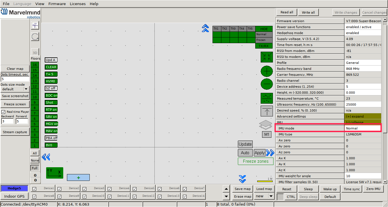
When you have the map, and mobile beacon is mounted on the rover, you can turn it on following the steps for stationary beacons (turn on the power of the beacon, wake it up in the dashboard, input height). After you have done those steps, mobile beacon should be traceable in 5–7 seconds. The system is now fully operational.
Right now, the only way we see the estimated position of the rover is in the dashboard. But it would be more useful to integrate the Marvelmind navigation system with ROS, as it will allow us to do anything with the position (for example, navigating the rover).
To do so, we utilize leo_marvelmind package which provides:
First you need to download our leo_marvelmind package, from github repository. To do so, connect to the rover via ssh. Once you are connected, you need to download the package in your ros workspace, in the src directory. If it's in your home directory, type:
Now we need to install all required rosdep dependencies:
And in the end, if everything installed successfully, you have to build the package
The rover should be aware of where the beacon is located, and what space it occupies. You can ensure it does that by making URDF model of the beacon.
We will have separate URDF file for the beacon model, and we will link it to the rover's URDF.
Our beacon model is 5.5 x 5.5 x 6.5 cm large, and we mounted it 7 cm in front of the mounting hole that serves as a base link in robot's URDF model. Therefore, our beacon URDF model looks like this:
Now, we need to link it to the main urdf file. To do so, you need to inlcude this line in /etc/ros/robot.urdf.xacro file (somewhere between <robot> and </robot> tags):
Now, to make beacon visible for the rover, you need to reboot the robot, or restart leo service:
Lists of parameters for parsers are in the leo_marvelmind/config directory. Except for subscribed/published topic names, there are also covariances, so you can change those at your convenience.
You can run all nodes using marvelmind_localization.launch file by sourcing the devel directory and typing command
Here's a diagram that illustrates the nodes launched by the marvelmind_localization.launch file and the connections between them:
Then, you can also run rviz (on your computer if it is not installed on the rover – you need to export ros variables) and add robot model, and visualize the estimated position (remember to chose map as fixed frame).
Now, that you know how to use indoor GPS you might want to learn about outdoor GPS. Check out our tutorial on Ublox GPS Module. Or go to our Knowledge Base site, where you can find more tutorials on a range of topics.
Find us on:
